

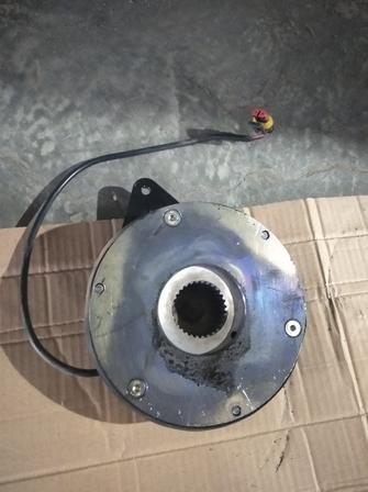
- Safety redundancy design
Electromagnetic brakes are critical safety components that must lock reliably when power fails. A 96V coil would risk brake failure if the controller’s high-voltage circuit malfunctions. Independent 48V low-voltage power supply adds an extra safety layer.
- Coil universal compatibility
48V electromagnetic brakes are mass-produced standard parts with low costs and stable supply. 96V coils require custom manufacturing, featuring long lead times and higher prices — unnecessary extra expense for voltage matching.
- Reliable pull-in performance
Brake pull-in only requires sufficient ampere-turns. The 48V coil receives steady current via a DC-DC step-down module from the 96V main circuit for consistent, reliable engagement. Low-voltage coils also have lower insulation grade requirements and lower failure rates.
2. Fault Tree Breakdown: 8 Root Causes of Brake Failure
Cause 1: Debris, bulges or burrs between stator and armature plate
Cause 2: Uneven or contaminated mounting interface between motor and brake
Cause 3: Excessive perpendicularity error of the brake friction disc
Cause 4: Improper wiring of the brake assembly
Cause 5: Deformation from hammering during installation
Cause 6: Unfixed spline hub of the brake assembly
Cause 7: Undervoltage at brake startup
Cause 8: Open circuit or failed insulation of the brake coil
3. Three Hidden Pitfalls Unique to 96V + 48V Brake Systems
Pitfall 1: Undersized DC-DC converter with heavy-load voltage drop
Pitfall 2: Common-ground interference triggering unintended brake actuation
Pitfall 3: High-voltage leakage destroying the brake coil
4. Step-by-Step Troubleshooting Workflow (From Simple to Complex)
- Measure operating voltage
Test the actual voltage across the brake coil under energized load conditions, not with power disconnected.
If readings fall below 90% of rated voltage (below 43V for 48V brakes), resolve power supply issues before disassembling the brake.
- Measure coil resistance (power off)
Compare measured coil resistance to the nominal specification. Infinite resistance indicates an open coil; abnormally low resistance signals inter-turn short circuits.
Also test coil-to-ground insulation resistance: infinite resistance is normal. Any measurable resistance confirms insulation failure.
- Independent bench power test
Unplug the vehicle harness and power the brake directly with a dedicated 48V power supply to test release function.
- Normal operation on bench test: the brake assembly itself is intact; faults lie within wiring, DC-DC converter or controller.
- Failed release on bench test: the brake unit has internal defects, proceed to further disassembly inspection.
- Inspect mounting interfaces
Remove the brake and examine the motor end cover for dents, debris or deformation, and check the brake spigot for damage. Cleaning the surfaces and reinstalling often resolves the fault.
- Inspect mating surfaces
Disassemble the brake and check the stator and armature plates for bulges, burrs, debris or rust. Minor burrs/rust may be polished flat with fine sandpaper; severe deformation or bulges require full brake replacement.
- Inspect splines and hub assembly
Check for loose axial play and worn/deformed spline teeth. Install circlips or set screws to eliminate axial movement if the hub lacks positioning hardware.
- Test friction disc perpendicularity
Use a dial indicator to measure end runout of the friction disc and verify compliance with perpendicularity tolerances.
If out of spec, replace the defective friction disc or re-calibrate motor shaft alignment accordingly.
5. Corrective Solutions & Preventive Measures
- Mating surface defects: Light polishing for minor damage; full brake replacement for severe deformation.
Prevention: Clean all mating surfaces pre-assembly, wear gloves to avoid iron filings and dust contamination.
- Damaged mounting interfaces: Clean surfaces, repair dents, reinstall correctly.
Prevention: Protect mounting surfaces during handling and assembly; prohibit impact damage.
- Perpendicularity errors: Replace qualified friction discs or re-align assembly.
Prevention: Randomly inspect disc perpendicularity upon incoming parts delivery; recheck after assembly.
- Wiring faults: Rewire harnesses, replace faulty connectors, add waterproof sealing.
Prevention: Use distinct wire colors or dedicated connectors to separate 48V and 96V circuits and prevent misconnection.
- Undervoltage supply: Upgrade to a higher-power DC-DC converter, increase wire gauge to reduce line voltage drop.
Prevention: Reserve ≥30% power margin when selecting DC-DC modules; use wiring no thinner than 0.75mm² for brake power circuits.
- Burnt coils: Replace the coil or full brake assembly, identify and eliminate high-voltage leakage sources.
Prevention: Reinforce insulation between high-voltage and low-voltage circuits; double-check wiring voltage ratings during assembly.

