
Electromagnetic Brake Malfunction in 96V Systems: 8 Major Fault Causes & Troubleshooting Guide

image
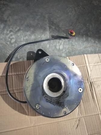
Electromagnetic Brake Assembly

Why 96V Motors Are Matched With 48V Electromagnetic Brakes

Engineers developing electric vehicle controllers often encounter a seemingly contradictory configuration: a 96V motor and controller paired with a 48V electromagnetic brake.
Many junior engineers wonder: Will mismatched voltages burn the brake coil?
The answer is no — this setup is standard industry practice.
Electromagnetic brakes (also called power-off brakes) operate on the principle of energize to release, de-energize to lock. When the coil is powered, electromagnetic force pulls the armature plate away, releasing the brake. Once power cuts off, springs push the armature back to clamp the friction disc and achieve braking.
Three core reasons explain why 96V systems avoid 96V brake coils:
  1. Safety redundancy design

    Electromagnetic brakes are critical safety components that must lock reliably when power fails. A 96V coil would risk brake failure if the controller’s high-voltage circuit malfunctions. Independent 48V low-voltage power supply adds an extra safety layer.

  2. Coil universal compatibility

    48V electromagnetic brakes are mass-produced standard parts with low costs and stable supply. 96V coils require custom manufacturing, featuring long lead times and higher prices — unnecessary extra expense for voltage matching.

  3. Reliable pull-in performance

    Brake pull-in only requires sufficient ampere-turns. The 48V coil receives steady current via a DC-DC step-down module from the 96V main circuit for consistent, reliable engagement. Low-voltage coils also have lower insulation grade requirements and lower failure rates.

However, this mismatched voltage design creates unique failure modes. This article fully breaks down electromagnetic brake malfunctions in 96V systems with a fault tree analysis.

2. Fault Tree Breakdown: 8 Root Causes of Brake Failure

Broadly speaking, failed brakes fall into two categories: failing to release when power is applied, or failing to lock when power cuts off. The underlying root causes are far more complex, detailed below:

Cause 1: Debris, bulges or burrs between stator and armature plate

This is the most common and frequently overlooked fault. The mating surfaces of electromagnetic brakes demand perfect flatness. Even tiny debris, burrs or surface bulges create air gaps between the stator and armature, drastically reducing electromagnetic pulling force.
96V high-power motors generate large braking torque with correspondingly large mating surfaces, raising flatness requirements. Even a tiny iron chip left during assembly can prevent full brake release, creating a partial drag state.
Typical symptoms: Partial brake engagement, persistent friction noise during motor rotation; normal operation when cold, dragging after heat buildup.

Cause 2: Uneven or contaminated mounting interface between motor and brake

Electromagnetic brakes mount to the motor end cover via spigot positioning. Dents, debris or deformation on the mounting surface tilt the entire brake assembly.
Tilt causes uneven wear on the mating surfaces: one side engages fully while the other remains separated, resulting in insufficient overall pulling force.
This issue is amplified on high-power 96V motors, which feature large, heavy end covers. Minor dents from careless handling during assembly become hidden failure risks.

Cause 3: Excessive perpendicularity error of the brake friction disc

The friction disc rotates synchronously with the motor shaft, and its perpendicularity directly determines brake reliability.
If the disc itself is warped, or misaligned with the motor shaft post-installation, partial friction or jamming occurs during rotation. Symptoms include periodic rotational resistance, heavy rotation at specific angular positions, or complete seizure.
For heavy-duty 96V vehicles with high braking torque, perpendicularity defects are exacerbated and more likely to trigger faults.

Cause 4: Improper wiring of the brake assembly

While this seems straightforward, wiring defects account for a large share of after-sales failures.
Electromagnetic brakes use a 2-wire positive/negative harness. On 96V systems designed for 48V brakes, reverse polarity or accidental connection to the 96V high-voltage bus instantly burns the coil.
Another prevalent issue is poor connector contact: vibration, water intrusion or oxidation increases contact resistance, lowering coil voltage and weakening pull-in force.
Intermittent power supply leads to far more severe secondary damage: sporadic partial braking generates friction heat, thermal expansion worsens abrasion, and eventually results in permanent full lock-up. Initial minor contact issues escalate into complete brake seizure over time.

Cause 5: Deformation from hammering during installation

Electromagnetic brakes are precision components highly vulnerable to impact damage. Many assembly technicians shortcut installation by hammering the brake into position.
A single hammer strike can deform splines, skew the armature plate, or indent the stator mating surface. The brake may operate temporarily, but degraded precision leads to faults emerging after weeks or months of use, making diagnosis difficult.
Assembly-induced precision defects such as spline deformation trigger abnormal wear with delayed failure onset.

Cause 6: Unfixed spline hub of the brake assembly

The brake’s spline hub slides onto the motor shaft. Without secure axial positioning, the hub shifts back and forth during rotation, causing abnormal friction and premature failure of the spline assembly or rotor.
This problem is pronounced on high-speed, high-torque 96V motors. Loose hubs create axial play and accelerated wear.
Typical symptoms: abnormal brake noise; smooth low-speed operation with friction or seizure at high speeds.

Cause 7: Undervoltage at brake startup

This is the most frequent failure mode for 48V brakes paired with 96V systems.
Sufficient voltage is mandatory to generate enough electromagnetic force to retract the armature plate. Insufficient voltage results in weak pull-in or total failure to release.
The 48V brake power supply on 96V vehicles is derived from the main 96V bus via a DC-DC step-down converter. Low DC-DC output voltage or excessive line voltage drop can reduce the actual voltage reaching the brake coil below its rated operating range.
For a 48V brake rated for 42V–54V operation, a real-world supply of only 38V drastically weakens magnetic force. Common symptoms include reliable cold-start release but failure after warming, or intermittent release performance.
This fault is easily misdiagnosed: a multimeter may read nominal voltage under no load, which collapses drastically once the brake coil draws current.

Cause 8: Open circuit or failed insulation of the brake coil

This is the most severe and easily identifiable fault: a burnt or broken coil shows zero response when powered, leaving the brake permanently locked.
Coil burnout in 96V systems rarely stems from insufficient 48V supply; the primary trigger is accidental connection to the 96V high-voltage bus. Applying 96V to a 48V coil burns it out within seconds.
A secondary failure mode is degraded insulation leading to coil-to-ground short circuits, common in damp or water-exposed operating environments.

3. Three Hidden Pitfalls Unique to 96V + 48V Brake Systems

Even veteran engineers frequently encounter these system-specific hidden risks:

Pitfall 1: Undersized DC-DC converter with heavy-load voltage drop

Many technicians select DC-DC modules based solely on output voltage, ignoring power rating. Brake coils draw large inrush current (several amps) during initial pull-in.
If the DC-DC lacks adequate power margin, the bus voltage collapses the instant the brake energizes, causing weak or intermittent release. The no-load voltage may read a normal 48V, yet drop below 40V under load — misleading inexperienced maintenance staff.

Pitfall 2: Common-ground interference triggering unintended brake actuation

Poor separation between the 96V power ground and 48V brake ground creates cross-interference.
Symptoms: abnormal brake response as the motor spins, or partial lock-up under heavy throttle. Large current flow creates voltage potential differences across the power ground plane, distorting the coil supply voltage via shared grounding points. This fault is notoriously hard to trace.

Pitfall 3: High-voltage leakage destroying the brake coil

The deadliest risk. Poor insulation between the 96V high-voltage circuit and 48V low-voltage brake circuit allows high voltage to leak into the low-voltage side, instantly destroying the 48V coil.
A more dangerous latent failure mode is partial insulation breakdown: normal cold operation, but degraded insulation at high temperatures allows gradual high-voltage leakage, slowly overheating and burning the coil. This fault manifests weeks after vehicle assembly, posing severe safety hazards.

4. Step-by-Step Troubleshooting Workflow (From Simple to Complex)

Do not disassemble the brake immediately upon detecting malfunctions. Follow this ordered workflow for maximum diagnostic efficiency:
  1. Measure operating voltage

    Test the actual voltage across the brake coil under energized load conditions, not with power disconnected.

    If readings fall below 90% of rated voltage (below 43V for 48V brakes), resolve power supply issues before disassembling the brake.

  2. Measure coil resistance (power off)

    Compare measured coil resistance to the nominal specification. Infinite resistance indicates an open coil; abnormally low resistance signals inter-turn short circuits.

    Also test coil-to-ground insulation resistance: infinite resistance is normal. Any measurable resistance confirms insulation failure.

  3. Independent bench power test

    Unplug the vehicle harness and power the brake directly with a dedicated 48V power supply to test release function.

    • Normal operation on bench test: the brake assembly itself is intact; faults lie within wiring, DC-DC converter or controller.
    • Failed release on bench test: the brake unit has internal defects, proceed to further disassembly inspection.
  4. Inspect mounting interfaces

    Remove the brake and examine the motor end cover for dents, debris or deformation, and check the brake spigot for damage. Cleaning the surfaces and reinstalling often resolves the fault.

  5. Inspect mating surfaces

    Disassemble the brake and check the stator and armature plates for bulges, burrs, debris or rust. Minor burrs/rust may be polished flat with fine sandpaper; severe deformation or bulges require full brake replacement.

  6. Inspect splines and hub assembly

    Check for loose axial play and worn/deformed spline teeth. Install circlips or set screws to eliminate axial movement if the hub lacks positioning hardware.

  7. Test friction disc perpendicularity

    Use a dial indicator to measure end runout of the friction disc and verify compliance with perpendicularity tolerances.

    If out of spec, replace the defective friction disc or re-calibrate motor shaft alignment accordingly.

5. Corrective Solutions & Preventive Measures

Targeted fixes and long-term prevention for each fault mode:
  • Mating surface defects: Light polishing for minor damage; full brake replacement for severe deformation.

    Prevention: Clean all mating surfaces pre-assembly, wear gloves to avoid iron filings and dust contamination.

  • Damaged mounting interfaces: Clean surfaces, repair dents, reinstall correctly.

    Prevention: Protect mounting surfaces during handling and assembly; prohibit impact damage.

  • Perpendicularity errors: Replace qualified friction discs or re-align assembly.

    Prevention: Randomly inspect disc perpendicularity upon incoming parts delivery; recheck after assembly.

  • Wiring faults: Rewire harnesses, replace faulty connectors, add waterproof sealing.

    Prevention: Use distinct wire colors or dedicated connectors to separate 48V and 96V circuits and prevent misconnection.

  • Undervoltage supply: Upgrade to a higher-power DC-DC converter, increase wire gauge to reduce line voltage drop.

    Prevention: Reserve ≥30% power margin when selecting DC-DC modules; use wiring no thinner than 0.75mm² for brake power circuits.

  • Burnt coils: Replace the coil or full brake assembly, identify and eliminate high-voltage leakage sources.

    Prevention: Reinforce insulation between high-voltage and low-voltage circuits; double-check wiring voltage ratings during assembly.


Previous Post

Troubleshooting Spontaneous Rotation Fault of 48V Controller Motor: Root Causes and Solutions for Low Sampling Values

Next Post

In-Depth Analysis of DC-DC Converter Working Principle & Vehicle Power Management

Leave a Reply

Shopping cart