

DC-DC Converter: More Than a Charger, the Core of Vehicle Low-Voltage Power Supply
Some think it only charges the auxiliary battery and worry that prolonged charging will cause overcharging and fire hazards; others believe it should operate 24/7 and wonder why it cuts out once the vehicle is turned off. Some users assume the DC-DC can be powered off at will since the auxiliary battery provides backup power; meanwhile, whenever their auxiliary battery runs flat, they immediately suspect the DC-DC has failed.
01 Basic Definition: What Exactly Is a DC-DC Converter?
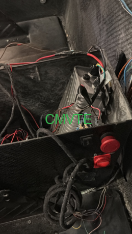
Electric vehicles are equipped with high-voltage main batteries (48V, 72V, 96V or higher) that supply power to drive the traction motor. However, all auxiliary on-board devices including headlights, horns, instrument panels, central control systems and windscreen wipers run on 12V low voltage. The DC-DC converter converts high voltage from the main battery into stable 12V low voltage to power all these vehicle accessories.
Most people mistakenly believe the DC-DC’s main job is to charge the auxiliary battery while secondarily powering electrical loads. In reality, the priority is reversed: the DC-DC’s core function is to supply power to all 12V vehicle devices, and the small auxiliary battery only serves as an energy storage buffer connected to the same power bus.
02 Operating Mechanism: Why the DC-DC Will Not Overcharge the Auxiliary Battery
-
Parallel connection to the 12V main bus
The output terminal of the DC-DC, the 12V auxiliary battery and all 12V electrical loads are wired in parallel on the unified vehicle 12V power bus. This means the 12V power output by the DC-DC directly feeds vehicle accessories, rather than passing through the battery first. The auxiliary battery only acts as a parallel energy storage unit: it draws minimal current under light load conditions and discharges to stabilize voltage during power surges. It functions as a voltage stabilizer and peak power buffer, not a mandatory power transit path.
-
Current absorption ceases once the battery is fully charged
Nearly all vehicle 12V auxiliary batteries are lead-acid types, which possess an inherent chemical property: once fully charged, the terminal voltage matches the charging voltage, and the battery stops drawing input current automatically. This natural characteristic requires no complex protective circuits. A fully charged battery is comparable to a full cup — no more liquid can be poured in. All current output from the DC-DC flows directly to active electrical devices, with the battery remaining idle without charging or discharging.
-
Regulated output voltage
Qualified DC-DC converters maintain a steady output voltage of approximately 13.8V. This voltage level delivers safe float charging for lead-acid batteries without reaching thresholds that trigger overcharging. This principle mirrors mobile phone chargers with fixed 5V output: leaving the phone plugged in overnight will not damage its battery from continuous charging.
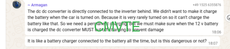
03 Common Misconception: Why the DC-DC Stops Working After Vehicle Shutdown
Theoretically this is achievable, yet modification of the DC-DC hardware alone cannot realize this function.
- Prevent accidental depletion of the high-voltage main battery. The DC-DC consumes static power during continuous operation, which can fully drain the main battery after prolonged idle periods.
- Improve safety. The high-voltage system should be fully de-energized when the vehicle is parked. Persistent DC-DC operation maintains continuity of the high-voltage circuit, introducing potential safety risks.
04 Three-Step Fault Diagnosis Framework
Step 1: Verify whether the DC-DC is active
In many cases, the root issue is not a defective DC-DC, but failure to trigger its enable signal. Use a multimeter to measure voltage at the DC-DC output terminal or the two poles of the 12V auxiliary battery under vehicle power-on state.
- Normal operation: Voltage reads between 13V and 14V
- Abnormal output / inactive status: Voltage stays around 12V or lower
Note: Measurements must be taken with the vehicle powered on; shutdown inactivity is normal.
If the DC-DC outputs above 13V normally yet 12V accessories malfunction or the auxiliary battery remains depleted, the fault likely lies outside the DC-DC unit:
- Aging auxiliary battery: Lead-acid batteries degrade after 2–3 years of service and lose charge retention capacity, discharging rapidly once the vehicle shuts down. Replacing the battery resolves this issue.
- Excessive electrical load: Total power draw of accessories exceeds the DC-DC’s rated power (common ratings: 300W, 500W). The bus voltage drops, forcing the auxiliary battery to discharge continuously. Solutions include removing unnecessary loads or upgrading to a higher-power DC-DC converter.
If zero output is detected after powering on the vehicle, do not immediately replace the DC-DC unit. First inspect the enable signal input: confirm whether the vehicle control unit transmits the operation command.
- Normal enable signal with no output: The DC-DC hardware itself is damaged.
- Absent enable signal: The fault originates from the vehicle control unit or key switch, unrelated to the DC-DC converter.
05 Operating Limits of DC-DC Converters
Capabilities
- Convert high voltage from the main battery into stable 12V low voltage
- Supply continuous power to all vehicle 12V electrical accessories
- Provide supplementary float charging to the 12V auxiliary battery while powering loads
- Cooperate with the auxiliary battery to stabilize voltage during power demand surges
Limitations
- Cannot autonomously activate or shut down (operation controlled by the vehicle system)
- Subject to fixed rated power, unable to supply unlimited power
- Cannot repair degraded, aged auxiliary batteries
- Cannot replace the battery’s function as a peak power buffer

