

Permanent Magnet Synchronous Motors (PMSMs) are widely used in modern electric vehicles because they can deliver high efficiency, strong torque, and precise speed control in a relatively compact design.
But how does a PMSM motor actually work?
Unlike an internal combustion engine, which generates mechanical power through fuel combustion, a PMSM converts electrical energy into mechanical rotation through the interaction of magnetic fields.
The process involves several key components working together: the stator, rotor, permanent magnets, motor controller, and inverter. Each plays an important role in controlling how the motor starts, accelerates, and produces torque.
Understanding the PMSM motor working principle helps explain why this motor technology is widely used in EV powertrains and why selecting a properly matched motor and controller is essential for a successful electric vehicle conversion.
What Is a Permanent Magnet Synchronous Motor?
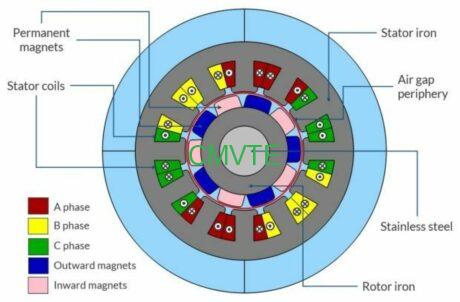
A Permanent Magnet Synchronous Motor (PMSM) is an AC electric motor that uses permanent magnets installed in its rotor to create a constant magnetic field.
Its stator contains three-phase windings that generate a rotating magnetic field when supplied with controlled three-phase AC current.
The interaction between these two magnetic fields produces electromagnetic torque, causing the rotor to rotate.
The term “synchronous” describes the relationship between the rotor’s rotational speed and the rotating magnetic field generated by the stator. Under normal synchronous operation, the rotor remains synchronized with the stator field.
Unlike an induction motor, a PMSM does not need to induce current in the rotor to establish its main magnetic field. The permanent magnets provide that field directly.
This design contributes to several important characteristics:
- High electrical-to-mechanical energy conversion efficiency
- High torque density
- Compact motor dimensions
- Precise speed and torque control
- No rotor excitation winding losses
These characteristics make PMSM technology particularly suitable for electric vehicle propulsion systems.
Main Components of a PMSM Motor
Before understanding how the motor works, it is important to understand its basic construction.
A typical PMSM consists of several major components.
1. Stator: Generating the Rotating Magnetic Field
The stator is the stationary outer part of the motor.
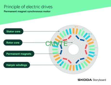
It contains a laminated steel core and three-phase copper windings arranged in slots around the motor’s inner circumference.
When three-phase AC current flows through these windings, it creates a rotating magnetic field inside the motor.
The speed and direction of this magnetic field depend on the electrical supply frequency and phase sequence.
The stator is therefore responsible for generating the magnetic field that drives the rotor.
2. Rotor: Providing the Permanent Magnetic Field
The rotor is the rotating part located inside the stator.
Unlike an induction motor rotor, a PMSM rotor contains permanent magnets that generate its magnetic field without requiring external electrical excitation.
The magnets can be arranged in different configurations.
Two common designs are:
Surface Permanent Magnet (SPM) Rotor
The permanent magnets are mounted on the surface of the rotor core.
This design provides a relatively simple magnetic structure and is commonly used in applications requiring smooth torque production.
Interior Permanent Magnet (IPM) Rotor
The permanent magnets are embedded inside the rotor core.
This configuration can provide additional reluctance torque and mechanical advantages at higher rotational speeds, depending on the design.
The choice between these rotor structures affects the motor’s torque characteristics, efficiency, speed range, and control requirements.
3. Motor Controller and Inverter
The motor controller is responsible for managing the electrical power delivered to the motor.
In an electric vehicle, the battery supplies DC electricity. The inverter inside the motor controller converts this DC power into controlled three-phase AC power for the stator windings.
The controller also manages important operating parameters, including:
- Motor speed
- Torque output
- Phase current
- Acceleration response
- Regenerative braking, where supported
- Motor protection
It uses rotor position information, obtained through sensors or estimated through sensorless control algorithms, to coordinate the electrical current supplied to the stator.
Without an appropriately matched controller, a PMSM cannot operate as intended.
How Does a PMSM Motor Work?
The working principle of a PMSM motor is based on the interaction between the rotating magnetic field of the stator and the permanent magnetic field of the rotor.
The entire process can be divided into several stages.
Step 1: DC Power Comes from the Battery
In an electric vehicle, the battery pack stores electrical energy in DC form.
When the driver presses the accelerator pedal, the vehicle control system sends a torque or speed request to the motor controller.
The controller then determines how much electrical power the motor needs.
Step 2: The Inverter Converts DC into Three-Phase AC
The battery cannot directly provide the controlled three-phase AC waveform required by a typical PMSM.
The inverter converts the battery’s DC power into three-phase AC electricity.
By controlling the current supplied to the stator windings, the inverter determines the characteristics of the magnetic field generated inside the motor.
The electrical frequency influences the rotating field’s speed, while the current magnitude and phase influence torque production.
Step 3: The Stator Generates a Rotating Magnetic Field
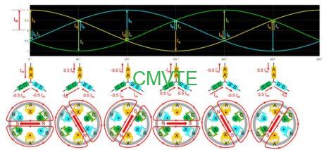
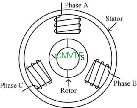
When three-phase currents flow through the stator windings, they create a magnetic field that continuously rotates around the motor.
The three phases are electrically separated by 120 degrees.
Their combined magnetic effects produce a rotating magnetic field rather than a stationary one.
This rotating field provides the driving force that interacts with the rotor’s permanent magnets.
Step 4: The Rotor Magnets Follow the Rotating Field
The permanent magnets inside the rotor create their own magnetic field.
As the stator’s magnetic field rotates, the rotor’s magnetic poles interact with it.
The rotor follows the rotating stator field and remains synchronized with it during normal operation.
This interaction generates electromagnetic torque, which causes the rotor shaft to turn.
Step 5: Electrical Energy Becomes Mechanical Power
Once the rotor starts rotating, the motor produces mechanical output through its shaft.
This mechanical power can then be transmitted through a gearbox, reduction unit, or other drivetrain components to drive the vehicle’s wheels.
The process can be summarized as:
Battery DC Power → Inverter → Three-Phase AC → Rotating Magnetic Field → Rotor Rotation → Mechanical Output
This is the fundamental working principle behind a PMSM-powered electric vehicle.
Watch: Working Principle of Permanent Magnet Synchronous Motors
Want to understand the PMSM working principle through a quick visual explanation?
Watch this CMVTE Short:
Watch: Working Principle of Permanent Magnet Synchronous Motors
The video provides a concise introduction to how a permanent magnet synchronous motor operates.
As shown in the explanation, the stator generates a rotating magnetic field, while the permanent magnets in the rotor interact with that field to produce rotational movement.
For a deeper understanding, the following sections explain how torque is generated and how the motor controller regulates the motor’s operation.
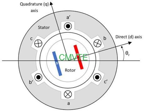
How Does a PMSM Motor Generate Torque?
Torque is the rotational force that allows an electric motor to drive a vehicle.
In a PMSM, torque is generated through the electromagnetic interaction between the stator current and the rotor’s permanent magnetic field.
When the rotor magnetic field and stator magnetic field are properly positioned relative to each other, an electromagnetic force acts on the rotor and produces rotation.
The magnitude of torque depends on several factors, including:
- Stator current
- Rotor magnetic flux
- Relative magnetic field position
- Motor electromagnetic design
- Control strategy
In an interior permanent magnet motor, the rotor’s magnetic reluctance characteristics can also contribute additional reluctance torque.
The Relationship Between Current and Torque
In a PMSM, the motor controller can regulate the stator current to control the electromagnetic torque.
In simplified terms, increasing the torque-producing current generally increases the motor’s available torque within its operating limits.
This is important for electric vehicles because different driving conditions require different torque levels.
For example:
- Starting from a standstill requires sufficient starting torque.
- Accelerating requires additional torque.
- Climbing a slope requires sustained torque.
- Cruising at a steady speed may require less torque, depending on road load.
The motor controller continuously adjusts the electrical input to meet the vehicle’s torque demand.
How Does Field-Oriented Control (FOC) Work?
Field-Oriented Control (FOC), also known as vector control, is a widely used control method for PMSM motors.
Its purpose is to provide precise control over motor torque and magnetic flux.
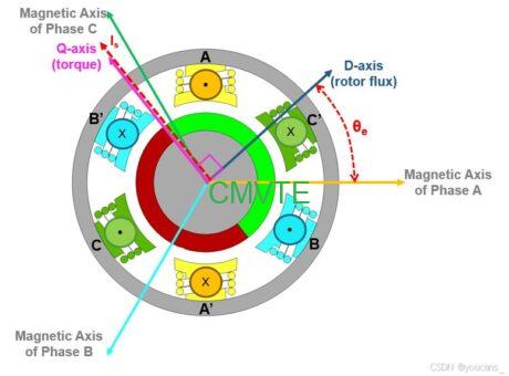
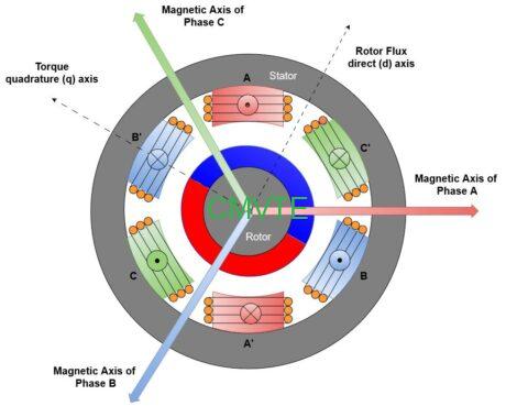
Instead of treating the three-phase currents as a single electrical quantity, FOC mathematically transforms them into two components in a rotating reference frame.
These are:
Direct-Axis Current (d-axis)
This current component is associated with the magnetic flux direction of the rotor.
Quadrature-Axis Current (q-axis)
This component is primarily responsible for producing electromagnetic torque.
By controlling these two current components independently, the controller can regulate motor torque and flux more precisely.
Why Is FOC Important for Electric Vehicles?
FOC provides several practical advantages:
- Smooth acceleration
- Precise torque response
- Improved low-speed control
- Efficient operation across different speed ranges
- Better control during changing driving conditions
For EV conversion projects, these characteristics are important because the electric motor must respond predictably to driver input while operating under different vehicle loads.
The controller and motor must therefore be properly matched to achieve the intended performance.
How Is PMSM Motor Speed Controlled?
The speed of a PMSM is closely related to the frequency of the rotating magnetic field generated by the stator.
For a conventional synchronous motor, the synchronous speed can be calculated using:
Ns = 120 × f / P
Where:
- Ns = Synchronous speed in revolutions per minute (RPM)
- f = Electrical frequency in hertz (Hz)
- P = Number of motor poles
For example, a four-pole motor supplied with an electrical frequency of 100 Hz has a synchronous speed of:
Ns = 120 × 100 / 4 = 3,000 RPM
In an EV application, the inverter controls the electrical frequency supplied to the motor.
Increasing the frequency increases the rotating magnetic field speed, allowing the rotor to operate at a higher synchronous speed.
However, actual motor speed and available torque also depend on voltage limits, current limits, motor design, and the controller’s operating strategy.
This is why a properly configured motor controller is essential for achieving the required vehicle performance.
What Happens During Regenerative Braking?
A PMSM can also operate as a generator under suitable operating conditions.
During regenerative braking, the vehicle’s kinetic energy drives the motor mechanically.
The motor then converts part of this mechanical energy into electrical energy, which can be returned to the battery through the inverter and battery management system.
The controller manages this process by regulating the motor’s electrical operation.
Regenerative braking can help recover energy that would otherwise be dissipated as heat through conventional friction braking.
However, the amount of recoverable energy depends on vehicle speed, battery acceptance limits, motor characteristics, controller settings, and driving conditions.
Regenerative braking does not replace the vehicle’s mechanical braking system.
Why Are PMSM Motors Used in Electric Vehicles?
PMSM motors are widely adopted in EV powertrains because their electromagnetic design offers a useful balance of efficiency, power density, torque performance, and controllability.
1. High Efficiency
The rotor uses permanent magnets instead of an electrically excited rotor winding.
This eliminates rotor excitation current and the associated rotor copper losses.
As a result, PMSM motors can achieve high efficiency across suitable operating conditions.
2. High Power Density
PMSM motors can provide substantial power and torque relative to their size.
This is particularly useful in EV conversions, where the available engine compartment and drivetrain installation space may be limited.
3. Strong Torque Performance
PMSM motors can deliver strong torque at low speeds when properly designed and controlled.
This helps electric vehicles accelerate from a standstill and handle different driving loads.
4. Precise Speed Control
With an appropriate motor controller and control algorithm, PMSM motors can respond accurately to accelerator input and changing operating conditions.
This contributes to smooth vehicle operation.
5. Flexible Application
PMSM technology can be used in different vehicle platforms, including:
- Passenger cars
- Classic car conversions
- Pickup trucks
- SUVs and 4×4 vehicles
- Commercial vehicles
- Buses and other electric transportation platforms
The appropriate motor power, voltage, cooling system, and controller configuration depend on the vehicle and its intended application.
PMSM Motor vs. BLDC Motor: What Is the Difference?
PMSM and Brushless DC (BLDC) motors both use permanent magnets in the rotor and electronically controlled stator windings.
However, they are commonly designed around different back-EMF waveforms and commutation strategies.
| Feature | PMSM | BLDC |
|---|---|---|
| Back-EMF waveform | Typically sinusoidal | Typically trapezoidal |
| Current waveform | Typically sinusoidal | Often six-step or trapezoidal |
| Common control method | Field-Oriented Control | Six-step commutation or FOC |
| Torque output | Typically smoother | Can have more torque ripple with six-step control |
| Applications | EVs, servo drives, industrial systems | Fans, pumps, compact electric drives |
The distinction is not absolute because modern motor designs and control methods can overlap.
For a more detailed comparison, read our guide to BLDC vs. PMSM Motors: Key Differences and Applications.
What Should You Consider When Selecting a PMSM Motor for EV Conversion?
Understanding the working principle is only the first step.
When selecting a PMSM motor for a vehicle conversion project, the motor must be matched to the complete vehicle powertrain.
Important considerations include:
Motor Power and Torque
The required power and torque depend on vehicle weight, target acceleration, maximum speed, terrain, and intended use.
A passenger car and a commercial truck will generally require different motor configurations.
Battery Voltage
The motor and controller must be compatible with the selected battery voltage.
The voltage configuration also influences current requirements, system architecture, and electrical component selection.
Motor Controller Compatibility
The controller must match the motor’s electrical characteristics and control requirements.
Incorrect matching can lead to poor performance, protection faults, or unreliable operation.
Cooling System
High-power electric motors generate heat during operation.
Depending on the motor design and power level, air cooling or liquid cooling may be appropriate.
Thermal management is particularly important for vehicles that operate under sustained high loads.
Drivetrain Compatibility
The motor must also be integrated with the vehicle’s transmission, reduction gearbox, adapter plate, coupling, or other drivetrain components.
Mechanical compatibility is just as important as electrical compatibility.
CMVTE PMSM Motor Systems for EV Conversion
CMVTE focuses on providing complete fuel-to-electric conversion solutions rather than supplying an isolated motor as a standalone replacement component.
A successful conversion requires the motor, controller, battery, charging equipment, drivetrain connections, and supporting electrical components to work together as an integrated system.
CMVTE provides PMSM motor systems for different vehicle conversion applications, with configurations ranging from passenger vehicles to pickup trucks and commercial vehicles.
Depending on the project requirements, a complete conversion system can include:
- Permanent magnet synchronous motor
- Matched motor controller
- Battery pack and BMS
- Motor mounting and adapter components
- Drivetrain coupling components
- On-board charger
- DC-DC converter
- Accelerator pedal
- Wiring harness
- Supporting electrical and safety components
The appropriate configuration depends on the original vehicle, target performance, battery voltage, available installation space, and intended driving conditions.
Matching the PMSM System to Different Vehicles
Different vehicles require different electric drivetrain solutions.
For example:
Classic Cars
Classic car conversions often require careful consideration of available installation space, original transmission compatibility, and battery placement.
Pickup Trucks and SUVs
These vehicles may require higher torque output and suitable drivetrain integration to handle their weight and intended driving conditions.
Commercial Vehicles
Commercial vehicle conversions often prioritize continuous operating performance, load requirements, thermal management, and system reliability.
A vehicle-specific approach helps ensure that the complete electric conversion system is designed around the actual application.
Why Choose a Complete PMSM Conversion System?
Selecting a motor based only on its rated power is not enough.
The motor must work together with the controller, battery, transmission, and other supporting components.
An integrated conversion solution helps address several important requirements:
- Motor and controller compatibility
- Battery voltage matching
- Electrical system integration
- Mechanical drivetrain adaptation
- Cooling system selection
- Charging and auxiliary power integration
- System testing before shipment
This system-level approach can reduce the challenges associated with sourcing unrelated components from different suppliers.
For businesses, workshops, and conversion specialists, working with a professional EV conversion system supplier can make project planning and component integration more straightforward.
Looking for a PMSM Motor System for Your EV Conversion?
Choosing the right PMSM motor is only one part of building a successful electric vehicle powertrain.
CMVTE provides complete EV conversion systems designed around different vehicle platforms and performance requirements.
Our team can help evaluate:
- Motor power and torque requirements
- Battery voltage and capacity
- Motor controller matching
- Transmission and drivetrain compatibility
- Cooling and supporting electrical components
Tell us your vehicle model and conversion requirements.
Frequently Asked Questions About PMSM Motor Working Principles
1. What is the basic working principle of a PMSM motor?
A PMSM operates through the interaction between the rotating magnetic field generated by the stator windings and the permanent magnetic field produced by the rotor magnets. This interaction generates electromagnetic torque and causes the rotor to rotate synchronously with the stator field.
2. Does a PMSM motor use AC or DC electricity?
A PMSM is an AC motor. In electric vehicles, the battery normally supplies DC electricity, which an inverter converts into controlled three-phase AC power for the motor.
3. Why does a PMSM motor need a controller?
A PMSM requires controlled electrical excitation to start and operate correctly. The motor controller regulates the three-phase current, electrical frequency, and rotor-field synchronization to control motor speed and torque.
4. What is the role of the permanent magnets in a PMSM?
The permanent magnets establish the rotor’s magnetic field without requiring electrical excitation current. This magnetic field interacts with the rotating magnetic field generated by the stator to produce torque.
5. What is the difference between a PMSM and an induction motor?
A PMSM uses permanent magnets to establish its rotor magnetic field, while an induction motor generates rotor current through electromagnetic induction. PMSMs do not require rotor excitation current and can offer high efficiency and power density.
6. What is FOC in a PMSM motor?
Field-Oriented Control (FOC) is a control strategy that separates stator current into direct-axis and quadrature-axis components. This allows the controller to regulate magnetic flux and electromagnetic torque more precisely.
7. Can a PMSM motor generate electricity?
Yes. A PMSM can operate as a generator when an external mechanical force drives its rotor. In electric vehicles, this principle is used during regenerative braking to convert part of the vehicle’s kinetic energy into electrical energy.
8. Are PMSM motors suitable for EV conversion?
Yes. PMSM motors are widely used in EV conversion projects because of their efficiency, torque characteristics, compact size, and precise controllability. However, the motor must be matched with a suitable controller, battery, drivetrain, and supporting components.
9. How do I choose the right PMSM motor for my vehicle?
Consider vehicle weight, required power and torque, target speed, battery voltage, cooling requirements, drivetrain configuration, and intended operating conditions. A complete system evaluation is recommended before selecting the motor.
Final Thoughts
The working principle of a Permanent Magnet Synchronous Motor is based on a relatively straightforward electromagnetic concept: a rotating magnetic field generated by the stator interacts with permanent magnets in the rotor to produce mechanical rotation.
However, achieving reliable performance requires more than this basic interaction.
The inverter must supply controlled three-phase current, the controller must maintain synchronization between the magnetic fields, and the motor must be properly matched with the battery and drivetrain.
For electric vehicle conversion projects, understanding these principles helps explain why motor selection and system integration are equally important.
Whether you are converting a classic car, pickup truck, SUV, or commercial vehicle, choosing a properly matched PMSM motor system is an important step toward building a reliable electric powertrain.
CMVTE provides complete EV conversion kits and integrated electric drivetrain solutions to help turn conventional fuel-powered vehicles into electric vehicles.
Contact CMVTE to discuss your vehicle platform, performance targets, and electric conversion requirements.

