

A permanent magnet motor may look like a compact metal housing from the outside, but its internal structure contains several precisely engineered components that work together to generate rotational power.
From the stator and rotor to the permanent magnets, motor shaft, bearings, and housing, every component has a specific function. Their design and interaction influence the motor’s torque output, efficiency, operating speed, thermal performance, and overall reliability.
For electric vehicle applications, understanding these components is especially important. A motor is not simply a power source that can be selected by its rated kilowatts. Its internal construction must also match the controller, battery system, drivetrain, and vehicle requirements.
In this guide, we take a closer look at the core components of a Permanent Magnet Synchronous Motor (PMSM), using a 3D structural perspective to explain what each part does and how the complete motor operates.
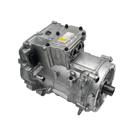
1. What Is a Permanent Magnet Motor?
A permanent magnet motor is an electric motor that uses permanent magnets to establish a magnetic field without requiring a separate electrical excitation winding for that field.
One widely used type is the Permanent Magnet Synchronous Motor (PMSM).
A typical PMSM consists of two main electromagnetic assemblies:
- Stator: The stationary part containing the magnetic core and electrical windings.
- Rotor: The rotating part containing permanent magnets and connected to the motor shaft.
When controlled three-phase AC current flows through the stator windings, it generates a rotating magnetic field. This field interacts with the permanent magnets in the rotor, producing electromagnetic torque and causing the rotor to rotate.
The motor also contains mechanical and structural components that support this electromagnetic process, maintain accurate alignment, and protect the internal assemblies.
To understand the complete structure, it is useful to examine the components individually.
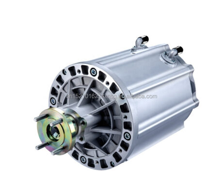
70KW PMSM motor for bus
2. Stator: The Stationary Electromagnetic Core
The stator is the stationary assembly surrounding the rotor in a typical radial-flux PMSM.
It is one of the most important components because it generates the rotating magnetic field that drives the rotor.
A typical stator consists of two major parts: the laminated stator core and the copper windings.
Stator Core
The stator core is generally constructed from multiple thin electrical steel laminations stacked together.
These laminations are designed to guide magnetic flux through the motor while helping reduce eddy-current losses.
Instead of using one solid piece of steel, laminated construction divides the conductive material into thin layers, limiting circulating currents generated by changing magnetic fields.
The inner surface of the stator core contains slots that accommodate the motor windings.
The number of slots, core dimensions, lamination material, and magnetic design all influence the motor’s electromagnetic characteristics.
Copper Windings
Copper windings are installed in the stator slots and arranged into electrical phases.
In a typical three-phase PMSM, the windings are supplied with three-phase AC current through the motor controller.
The current flowing through these windings produces the magnetic field required to drive the rotor.
Important winding design factors include:
- Wire size and conductor arrangement
- Number of turns
- Phase configuration
- Insulation quality
- Winding temperature limits
- Slot fill factor
These factors affect electrical resistance, current capacity, heat generation, and the motor’s overall performance.
The stator therefore serves as the electromagnetic foundation of the motor.
3. Rotor: The Rotating Magnetic Assembly
The rotor is positioned inside the stator and rotates when electromagnetic torque is generated.
In a PMSM, the rotor contains permanent magnets that establish its magnetic field.
The rotor assembly generally includes a rotor core, permanent magnets, and a shaft connection.
Rotor Core
The rotor core provides the mechanical structure that supports the permanent magnets and transfers torque to the motor shaft.
Like the stator, it may use laminated electrical steel to reduce magnetic losses.
Its geometry and magnetic properties influence flux distribution, torque characteristics, and the motor’s operating range.
The rotor must also maintain sufficient mechanical strength to withstand rotational forces during operation.
Permanent Magnets
Permanent magnets are the defining feature of a permanent magnet motor.
They provide the rotor’s magnetic field without requiring an additional electrical excitation winding.
High-performance PMSMs commonly use rare-earth permanent magnet materials such as neodymium-iron-boron (NdFeB), although the exact material depends on the motor design and application.
The magnets are arranged according to the rotor’s magnetic pole configuration.
Their grade, dimensions, temperature characteristics, and magnetic properties influence the motor’s torque capability and operating limits.
Two Common Rotor Structures
PMSM rotors are generally divided into two widely used configurations.
Surface Permanent Magnet (SPM) Rotor
In an SPM design, permanent magnets are mounted on the outer surface of the rotor core.
This arrangement provides a relatively straightforward magnetic structure and can offer favorable torque characteristics.
The mechanical retention of the magnets is particularly important because they are exposed to centrifugal forces during rotation.
Interior Permanent Magnet (IPM) Rotor
In an IPM design, permanent magnets are embedded inside the rotor core.
This arrangement can create magnetic reluctance differences along different rotor axes, allowing the motor to generate both magnet torque and reluctance torque.
IPM designs can also offer advantages in mechanical magnet retention and high-speed operation, depending on the specific engineering design.
The choice between SPM and IPM depends on the required torque, speed range, efficiency, mechanical strength, and manufacturing considerations.
For a more detailed comparison, read CMVTE’s article on Three Mainstream Structures of PMSM Motors.
4. Motor Shaft: Transferring Mechanical Power
The motor shaft connects the rotating assembly to the external drivetrain.
As the rotor turns, mechanical torque is transmitted through the shaft to a gearbox, reduction unit, coupling, or other connected equipment.
In an electric vehicle conversion, the shaft connection is particularly important because the motor must be integrated with the vehicle’s existing or redesigned drivetrain.
The shaft design must account for:
- Required torque transmission
- Rotational speed
- Shaft diameter and material
- Bearing support
- Coupling dimensions
- Alignment with the connected drivetrain
Incorrect alignment or an unsuitable coupling can cause vibration, noise, premature wear, or mechanical failure.
For this reason, motor shaft dimensions and mounting arrangements should be considered during the conversion design stage rather than after the motor has been selected.
5. Bearings: Supporting Smooth Rotor Rotation
Bearings support the motor shaft and allow the rotor to rotate while maintaining its intended position inside the stator.
They also help manage radial and axial loads generated during motor operation.
Bearing selection depends on factors such as:
- Operating speed
- Radial and axial load
- Temperature
- Lubrication requirements
- Expected service life
- Installation and alignment conditions
Proper bearing support is essential because the air gap between the stator and rotor must remain within the motor’s designed limits.
If the rotor becomes misaligned, it may cause uneven magnetic forces, vibration, increased mechanical friction, or contact between internal components.
Bearings are therefore small components with a major influence on motor reliability.
6. Motor Housing and End Covers: Protecting the Internal Structure
The motor housing forms the external structure that encloses and supports the internal assemblies.
It typically provides mechanical protection and helps maintain the alignment of the stator, rotor, and bearing assemblies.
Depending on the motor design, the housing may also contribute to heat dissipation or form part of an integrated cooling arrangement.
The end covers are installed at the ends of the motor housing. They support the bearing assemblies and help close and protect the internal motor structure.
Important housing design considerations include:
- Mechanical strength
- Structural rigidity
- Heat dissipation
- Environmental protection
- Mounting points
- Overall dimensions and weight
For vehicle conversion projects, motor dimensions and mounting locations must also be compatible with the available installation space.
7. Cooling System: Managing Motor Temperature
Motor temperature has a direct influence on electrical performance, insulation life, magnet characteristics, and operating reliability.
During operation, heat is generated by several sources, including winding resistance, magnetic losses, and mechanical losses.
A motor’s cooling system helps remove this heat and maintain an acceptable operating temperature.
Common approaches include:
Air Cooling
Air-cooled motors use airflow to remove heat from the motor housing and internal thermal paths.
Depending on the design, cooling may rely on natural airflow, external fans, or dedicated air passages.
Air cooling can offer a relatively simple structure, but its ability to remove heat depends on airflow and operating conditions.
Liquid Cooling
Liquid-cooled motors use a coolant circuit to transfer heat away from important motor components.
Depending on the motor design, cooling channels may be integrated into the motor housing or other thermal management structures.
Liquid cooling can provide more controlled heat removal and is particularly useful in higher-power applications where thermal management becomes more demanding.
CMVTE has a dedicated technical article explaining Liquid Cooling EV Motor Technology, including its role in electric vehicle thermal management.
8. Air Gap: The Critical Space Between Stator and Rotor
One important part of a motor’s internal structure is not a physical component at all.
It is the air gap: the small clearance between the stator and rotor.
Although this space is narrow, it plays an important role in electromagnetic performance and mechanical reliability.
The air gap allows the rotor to rotate without contacting the stator while enabling magnetic flux to pass between the two assemblies.
Its dimensions influence:
- Magnetic flux distribution
- Electromagnetic torque
- Magnetic forces
- Motor efficiency
- Mechanical tolerance requirements
A smaller air gap can influence magnetic coupling, but it also requires precise manufacturing and assembly tolerances.
The rotor must remain accurately centered during operation to avoid unwanted contact or uneven magnetic forces.
This is why the stator, rotor, shaft, bearings, and housing must be engineered as a coordinated mechanical assembly.
9. How These Components Work Together in an EV
Understanding individual motor components is useful, but the real value comes from seeing how they work together as a complete electric drive system.
In an electric vehicle, the motor does not operate independently.
The battery provides electrical energy, while the motor controller manages the electrical power supplied to the stator windings.
The process can be summarized as follows:
- The battery supplies DC electrical power.
- The inverter converts DC power into controlled three-phase AC.
- The stator windings generate a rotating magnetic field.
- The permanent magnets in the rotor interact with this field.
- Electromagnetic torque causes the rotor and shaft to rotate.
- The drivetrain transfers mechanical power to the wheels.
The motor controller also adjusts current and electrical timing according to driver input and operating conditions.
For PMSM applications, Field-Oriented Control (FOC) is commonly used to regulate torque and magnetic flux.
To learn more about this control strategy, explore CMVTE’s guide to Advanced Field-Oriented Control Technology for Automotive Motors.
10. Watch: Permanent Magnet Motor Close-Up in 3D
A written explanation can describe the function of each component, but a three-dimensional view makes the internal structure easier to understand.
In this short video, we take a closer look at the core components of a permanent magnet motor through a 3D view.
It provides a visual introduction to the motor’s internal construction and helps illustrate how the main assemblies fit together.
Watch the video:
Permanent Magnet Motor Close-up! 3D View of Core Components
For anyone learning about PMSM technology or evaluating an electric motor for an EV conversion project, understanding the motor’s internal construction is a useful starting point.
11. Why Motor Construction Matters in EV Conversion
When selecting an electric motor for a vehicle conversion, rated power is only one part of the decision.
The motor’s internal construction also influences its operating characteristics, thermal requirements, mechanical integration, and compatibility with the rest of the drive system.
Several factors should be considered.
Motor structure: SPM and IPM designs have different magnetic and mechanical characteristics.
Rated power and torque: The motor must provide suitable output for the vehicle’s weight and intended driving conditions.
Operating speed: The motor’s speed range must be compatible with the selected gearbox or reduction arrangement.
Cooling method: Air cooling or liquid cooling should be selected according to power level and operating requirements.
Mounting and shaft dimensions: The motor must fit the vehicle’s available space and connect correctly to the drivetrain.
Controller compatibility: The controller must support the motor’s electrical and control requirements.
A motor that looks suitable on paper may not be the right choice if its dimensions, speed range, torque characteristics, or controller requirements do not match the vehicle.
This is why professional EV conversion planning should consider the motor as part of a complete propulsion system.
12. CMVTE: Integrated Motor and EV Conversion System Solutions
CMVTE focuses on complete fuel-to-electric vehicle conversion solutions.
Rather than treating the motor as an isolated component, CMVTE considers how the motor, controller, battery, charger, wiring, drivetrain, and supporting electrical systems work together.
Depending on the vehicle and project requirements, an EV conversion package may include:
- Permanent magnet synchronous motor
- Matched motor controller
- Lithium battery pack and BMS
- On-board charger
- DC-DC converter
- Wiring harness and control components
- Adapter plates and drivetrain connection components
- Supporting systems such as electric power steering and braking components
The appropriate configuration depends on the donor vehicle, vehicle weight, installation space, target performance, and operating conditions.
CMVTE also provides technical information about motor structures, cooling methods, and control technologies to help customers better understand the engineering considerations behind an EV conversion.
Planning your own EV conversion project?
Share your vehicle model, weight, target speed, expected driving range, and drivetrain requirements with CMVTE.
Our team can help evaluate the suitable motor configuration and develop an integrated EV conversion solution for your vehicle.
Contact CMVTE for a Complete EV Conversion Solution
Frequently Asked Questions
1. What are the main components of a permanent magnet motor?
The main components of a typical permanent magnet synchronous motor include the stator, rotor, permanent magnets, motor shaft, bearings, housing, and end covers. Some designs also incorporate dedicated cooling passages or other thermal management components.
2. What is the function of the stator in a PMSM?
The stator contains the laminated magnetic core and electrical windings. When supplied with controlled three-phase AC current, it generates a rotating magnetic field that interacts with the rotor’s permanent magnets to produce torque.
3. What is the difference between an SPM and IPM rotor?
An SPM rotor has permanent magnets mounted on the surface of the rotor core. An IPM rotor has magnets embedded inside the rotor core. Their different magnetic and mechanical structures influence torque characteristics, speed capability, and design requirements.
4. Why does a PMSM use permanent magnets?
Permanent magnets establish the rotor’s magnetic field without requiring a separate electrical excitation winding. This helps reduce rotor excitation losses and supports compact, high-torque motor designs.
5. What does the motor shaft do?
The motor shaft transfers mechanical power from the rotating rotor assembly to the external drivetrain. In an EV conversion, it connects the motor output to a gearbox, reduction unit, or other mechanical transmission components.
6. Why is the air gap important in an electric motor?
The air gap is the clearance between the stator and rotor. It allows the rotor to rotate without contact while providing a path for magnetic flux. Its dimensions influence electromagnetic performance and mechanical tolerance requirements.
7. Do all permanent magnet motors use liquid cooling?
No. Cooling methods depend on motor power, design, operating conditions, and thermal requirements. Some motors use air cooling, while others use integrated liquid-cooling systems.
8. Does a PMSM require a special motor controller?
A PMSM requires a compatible controller capable of supplying and regulating the appropriate electrical currents. Controller voltage, current capacity, control method, and motor feedback requirements must match the specific motor.
9. Why is motor construction important for EV conversion?
Motor construction affects torque characteristics, speed range, cooling requirements, installation dimensions, and controller compatibility. These factors must be considered alongside vehicle weight and drivetrain design when selecting a conversion system.
Final Thoughts
A permanent magnet motor is made up of more than just a stator and rotor. Its permanent magnets, electrical windings, shaft, bearings, housing, cooling system, and internal clearances all contribute to its overall operation.
Each component performs a specific function, but none should be evaluated entirely in isolation. Their electromagnetic, mechanical, and thermal characteristics must work together to deliver reliable motor performance.
For electric vehicle conversion projects, understanding this internal structure helps buyers and engineers make more informed decisions when selecting motors and designing complete drive systems.
CMVTE focuses on integrated EV conversion solutions that combine appropriately matched motors, controllers, batteries, and supporting components.
Explore CMVTE’s motor technology and complete EV conversion solutions to find a configuration suited to your vehicle project.

