

The Real Question: "Do I Need HVIL for My DIY EV Conversion?"
A customer from Germany emailed us last month with his Toyota Hilux EV conversion project. He had the motor mounted, the battery pack installed, and the controller wired. Then he asked:
"I keep seeing 'HVIL' in wiring diagrams and DBC files. Do I actually need this for my conversion, or is it only for factory EVs? And if I need it, how do I implement it?"
This is one of the most common questions we get from serious DIY builders. The short answer: yes, you need HVIL if your system runs above 60V DC. It is not optional — it is the single most important safety mechanism standing between you and a high-voltage accident.
This article explains what HVIL is, why it matters for EV conversions (not just factory cars), and how CMVTE integrates HVIL into every wiring harness and high-voltage system we ship.
What is HVIL (High Voltage Interlock)?
HVIL (High-Voltage Interlock Loop) is a low-voltage safety monitoring circuit that continuously checks whether every high-voltage connector in your EV is properly seated, locked, and safe to energize.
Think of it as a 24/7 security guard for your high-voltage system. It runs a tiny 12V signal through every single high-voltage connector in series. If any connector comes loose, any cover is opened, or any harness is damaged—the signal breaks, and the system instantly shuts down high voltage before you can get hurt.
Without HVIL:
- You could pull a high-voltage connector while it's live → 400V DC arc, severe burns
- A loose connector during driving → intermittent arcing → connector meltdown, fire risk
- You open the battery cover to inspect cells → 360V DC still live inside
With HVIL: the system detects the disconnection in milliseconds and cuts power before the high-voltage pins even separate. This is achieved through the long/short pin design built into every modern high-voltage connector.
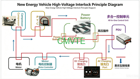
How HVIL Keeps You Safe: The Long/Short Pin Design
Every high-voltage connector in a properly designed EV system uses two types of pins:
| Pin Type | Function | Length | Connects First / Disconnects First |
|---|---|---|---|
| High-Voltage Pin | Carries main power (96V-400V) | Long | Connects first, disconnects last |
| HVIL Pin | Carries 12V monitoring signal | Short | Connects last, disconnects first |
| High-Voltage Pin | Carries main power (96V-400V) | Long | Connects first, disconnects last |
| HVIL Pin | Carries 12V monitoring signal | Short | Connects last, disconnects first |
The sequence matters:
Plugging in: HV pins touch → HVIL pins touch → BMS confirms loop is closed → high voltage is allowed to flow.
Unplugging: HVIL pin separates first → BMS detects loop break → high voltage is cut → HV pin separates (now safe, zero voltage).
This timing ensures you never pull a live high-voltage connector. By the time the high-voltage pins physically separate, the system is already de-energized.
DC HVIL vs. PWM HVIL: Which One Actually Works?
Not all HVIL implementations are equal. There are two approaches, and one has a serious blind spot:
| Feature | DC HVIL (5V or 12V constant) | PWM HVIL (1-5kHz pulsed signal) |
|---|---|---|
| Detects open circuit | Yes | Yes |
| Detects short to ground | No — signal just disappears | Yes — waveform shape change detected |
| Detects short to 12V | No — 12V looks like a valid signal | Yes — duty cycle distortion detected |
| Detects poor contact / resistance drift | No | Yes — amplitude change detected |
| EMI immunity | Poor | Excellent |
| False alarm rate | High | Very low |
The verdict: DC HVIL is like a simple on/off switch — it tells you the loop is broken, but not why or where. PWM HVIL is like a continuous health monitor — it detects degraded connections before they fail. That is why PWM-based HVIL is the standard in all modern production EVs, and why CMVTE uses it in our motor controllers and BMS systems.
Key HVIL Components in Your EV Build
A complete HVIL implementation for an EV conversion requires the following components, all connected in a single continuous series loop:
| Component | Role in HVIL Loop | CMVTE Product |
|---|---|---|
| BMS / VCU | Generates PWM signal and monitors return | Integrated BMS in battery packs |
| MSD (Manual Service Disconnect) | Emergency physical disconnect point | Included with battery packs |
| PDU (Power Distribution Unit) | Distributes HV to motor, charger, DC-DC | Available as part of battery system |
| Motor Controller | HVIL monitoring for motor power connection | CMVTE FOC controllers with HVIL support |
| High-Voltage Wiring Harness | Carries HV + integrates HVIL signal wire | Pre-built, pre-labeled harnesses |
| HV Connectors (with HVIL pins) | Long/short pin design for arc prevention | Included in complete kits |
| Battery Cover Switch | Opens HVIL if battery enclosure is opened | Battery-integrated |
CMVTE HVIL-Ready Wiring Harnesses and Safety Components
When you buy a complete CMVTE EV conversion kit, HVIL is not an afterthought — it is built into the system from the start:
- Pre-configured HVIL loop: Our wiring harnesses include the HVIL signal wire alongside every high-voltage cable. All connectors are pre-terminated with long/short pin contacts.
- PWM-based monitoring: Our BMS and VCU use PWM HVIL (not basic DC), giving you full fault diagnosis — open circuit, short to ground, short to 12V, resistance drift.
- Arc-free connectors: Every high-voltage connector in our kits uses the long/short pin design described above.
- Tested as a complete system: Motor → Controller → Battery → Charger → DC-DC — all HVIL points are pre-tested together, not pieced together from different suppliers.
This is the difference between "assembling parts from Alibaba" and "installing an engineered safety system." Ask us for a complete system wiring diagram for your vehicle.
Frequently Asked Questions
Do I really need HVIL for my DIY conversion? Isn't it overkill?
If your system voltage is above 60V DC, HVIL is not optional — it is a safety requirement in most jurisdictions (IEC 60664, ISO 6469-3). Even if not legally required in your country, HVIL is the difference between a loose connector being a minor issue and a 400V arc causing severe injury.
Can I implement HVIL with a simple 12V loop and a relay?
You can, but it provides only basic open-circuit detection. It will not detect a short to ground, a short to 12V, or a degraded connector with increased resistance. PWM-based HVIL (as used in CMVTE systems) catches all of these.
What happens when HVIL trips during driving?
The VCU/BMS detects the loop break in milliseconds, immediately opens the main high-voltage contactors, and the vehicle coasts to a stop. A fault code is stored for diagnosis. This is a designed safety response — not a system failure.
Does CMVTE include HVIL in all kits?
Yes. Every complete CMVTE conversion kit includes HVIL wiring, connectors, and BMS/VCU integration. If you are buying individual components, HVIL compatibility is specified in the datasheet. Contact us to confirm your configuration.
What voltage does the HVIL loop run at?
The HVIL monitoring signal runs at 12V (low voltage, safe to handle). It uses a separate, small-gauge wire that runs alongside the high-voltage cables. The monitoring signal itself is not dangerous.
Can I retrofit HVIL to an existing EV conversion?
Yes, but your high-voltage connectors must have the HVIL pin option. If your current connectors are basic 2-pin (HV+ and HV- only), you would need to upgrade to connectors with integrated HVIL pins. CMVTE can supply replacement HVIL-ready harnesses for most common EV conversion configurations.
Need Help with HVIL for Your Conversion?
If you're planning an EV conversion and want to ensure your high-voltage safety system is properly designed:
- Tell us about your build — vehicle, motor, battery voltage, and current state
- We'll send a safety review — including HVIL integration recommendations
- Get a quote for HVIL-ready components — harnesses, connectors, BMS, and controllers
Email us at [email protected] | WhatsApp: +86 181 2358 8272
Mention "HVIL Consultation" and describe your project. We'll respond within 24 hours.
Original article updated and expanded. By Kevin Wang, CEO of Green Motor Technology (GMT). Visit cmvte.com for our full product range.

