

Your motor controller, BMS, battery display, and OBC all talk to each other over a CAN bus network. If the termination resistors are wrong, they stop talking. No communication means no throttle response, no SOC reading, and in some cases, the vehicle won't even power on.
This is not a rare edge case. It's the #1 electrical support question CMVTE's engineering team receives from first-time builders. Here's how to get it right the first time.
What Is a CAN Termination Resistor and Why Should You Care?
CAN bus is a two-wire communication system (CAN_H and CAN_L). At each physical end of the bus, a 120 ohm resistor must be connected between the two wires. This resistor:
- Prevents signal reflection — without it, data bounces back and corrupts new transmissions
- Drains parasitic capacitance — lets the bus return to "recessive" state quickly between messages
- Stabilizes voltage levels — prevents electrical noise from being misinterpreted as data
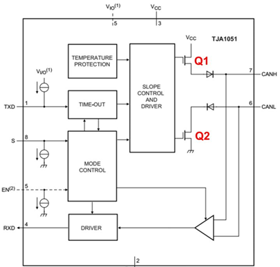
The ISO 11898 standard specifies 120 Ω because that matches the characteristic impedance of CAN twisted-pair cable. Two 120 Ω resistors in parallel at opposite ends of the bus give a total of ~60 Ω — the ideal load.
Mistake #1: No Termination Resistor (Open End)
This is the most common error. If one end of the CAN bus has no resistor, the signal hits an open circuit and reflects back. The reflected wave overlaps with the real signal, causing:
- Intermittent communication — works sometimes, fails randomly
- Error frames — the controller logs "bus off" errors
- Complete comms failure — motor won't respond to throttle
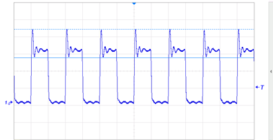
Check it: With system power off, measure resistance between CAN_H and CAN_L on your bus. A properly terminated system reads ~60 Ω. If you read 120 Ω, one resistor is missing. If you read > 10 kΩ, both are missing.
Mistake #2: Termination at Every Node (Too Many Resistors)
Many EV components — including some motor controllers and BMS units — have a built-in 120 Ω resistor that can be enabled with a jumper or switch. If you enable termination on every CAN node, the parallel resistance drops too low:
| Nodes with 120 Ω Enabled | Equivalent Bus Resistance | Result |
|---|---|---|
| 2 (correct) | 60 Ω | ✅ Normal operation |
| 3 | 40 Ω | ⚠️ Weak signal amplitude |
| 4 | 30 Ω | ❌ Transceiver overload, bus failure |
| 5 | 24 Ω | ❌ Complete communication breakdown |
Rule: Only the two devices at the physical ends of the CAN bus should have termination enabled. All devices in between must have termination disabled.
Mistake #3: Resistor in the Middle, Not at the End
If you place a termination resistor on a node in the middle of the bus, the signal traveling past that point sees an impedance discontinuity where the resistor is — and a second discontinuity at the actual bus end. This creates double reflection, which is harder to diagnose than a single open end.
The fix: Identify the two physically farthest-apart CAN devices on your network. Those are the only ones that get termination. In a typical CMVTE build:
- Motor controller — usually at one end of the bus
- Dashboard display — usually at the other end
- BMS, OBC, DC-DC — in between, termination disabled
How CMVTE Makes It Easy
CMVTE's FOC motor controllers and CAN dashboard displays come with clearly marked jumper pins for the 120 Ω termination resistor. The default position is disabled — you enable it only when the device is at the end of your bus.
- FOC Motor Controller — jumper JP1 for CAN termination, labeled on the enclosure
- CAN Dashboard Display — software-selectable termination in the settings menu
- BMS — termination disabled by default (designed for mid-bus installation)
Browse CMVTE CAN-enabled motor controllers →
Quick Diagnostic: 3-Step CAN Check
- Multimeter test (power off): Measure CAN_H to CAN_L. Target: 55-65 Ω. If 120 Ω → missing one resistor. If < 40 Ω → too many resistors.
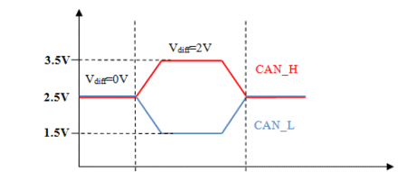
- Voltage test (power on): Measure CAN_H to GND (~2.5V) and CAN_L to GND (~2.5V). If one is near 0V or 5V, the transceiver may be damaged.
- Oscilloscope test: Look for clean square edges on the differential signal. Ringing or rounded edges → termination problem.
Still Having CAN Issues?
Send us a photo of your CAN bus wiring and the resistance reading between CAN_H and CAN_L. Our engineering team will identify the problem within one business day and send you the corrected wiring diagram.
WhatsApp / Phone: +86 181 2358 8272
Email: [email protected]
Mention "CAN Bus Help" and attach your multimeter reading photo.

