

Why Byte Order Matters in CAN Communication
If you have ever opened a DBC file and wondered why the same signal value reads completely differently depending on the byte order setting — you are not alone. Intel and Motorola formats are a classic source of confusion for EV engineers, especially when signals cross byte boundaries. This guide breaks down the difference with clear examples so you never misread a CAN signal again.
LSB and MSB — The Foundation
LSB (Least Significant Bit): The bit with the smallest weight in a binary number.
MSB (Most Significant Bit): The bit with the largest weight.
LSB and MSB describe the bit weight relationship within a value. They do not define transmission order or physical storage position. That is what byte order (Intel vs Motorola) defines.

Intel Format (Little-Endian)
Core rule: LSB at the low bit of the low byte, MSB at the high bit of the high byte.
Signal Within One Byte
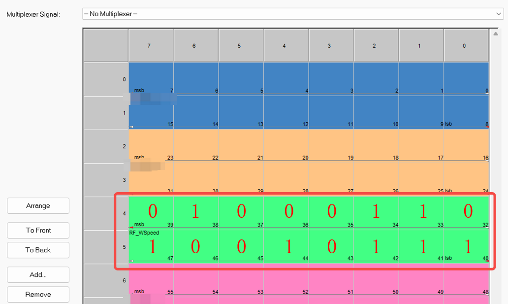
When a signal is fully contained in a single byte, both Intel and Motorola read the same: LSB at Bit 0, MSB at Bit 7. Example value 0100 0110 (0x46) reads from Bit 0 to Bit 7 within Byte 1.

Signal Across Multiple Bytes
With a 16-bit signal starting at Bit 0 of Byte 4 and ending at Bit 7 of Byte 5, Intel places the lower 8 bits (0x97) in Byte 4 (low address) and the upper 8 bits (0x46) in Byte 5 (high address). Read order: Byte 4 first (Bit 0 to 7), then Byte 5 (Bit 0 to 7). Result: 0100 0110 1001 0111 = 0x4697.

Motorola Format (Big-Endian)
Core rule: LSB in the low bit of the high byte, MSB in the high bit of the low byte.
Signal Within One Byte
Identical to Intel for single-byte signals. Example value 0x46 reads the same way.

Signal Across Multiple Bytes
For the same 16-bit signal, Motorola reverses the byte order. Byte 4 (low address) stores the upper 8 bits (0x46), and Byte 5 (high address) stores the lower 8 bits (0x97). Read order: Byte 4 first, then Byte 5. Result is still 0x4697, but the physical byte placement is swapped compared to Intel.
The Critical Difference in Memory
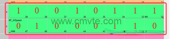
Although both formats produce the same binary value 0x4697, the physical memory layout is completely different:
- Motorola: Byte 4 (low address) = 0x46 (upper bits), Byte 5 (high address) = 0x97 (lower bits)
- Intel: Byte 4 (low address) = 0x97 (lower bits), Byte 5 (high address) = 0x46 (upper bits)
Fatal error: Reading Intel-layout data 0x4697 (Byte4=0x97, Byte5=0x46) using Motorola rules produces 0x9746 — a completely wrong signal value.
Quick Reference: Intel vs Motorola
| Aspect | Intel (Little-Endian) | Motorola (Big-Endian) |
| Low byte position | Lower address = lower bits | Lower address = upper bits |
| Signal start (LSB) | Low bit of low byte | Low bit of high byte |
| Single-byte signal | Same as Motorola | Same as Intel |
| Cross-byte signal | Byte order reversed vs Motorola | Byte order reversed vs Intel |
| Common in | PC/automotive (CAN) | Legacy/industrial (CAN) |
| LIN protocol | Mandatory | Not allowed |
Key Takeaways
- The starting point is always the LSB — both Intel and Motorola define the signal start at the LSB position.
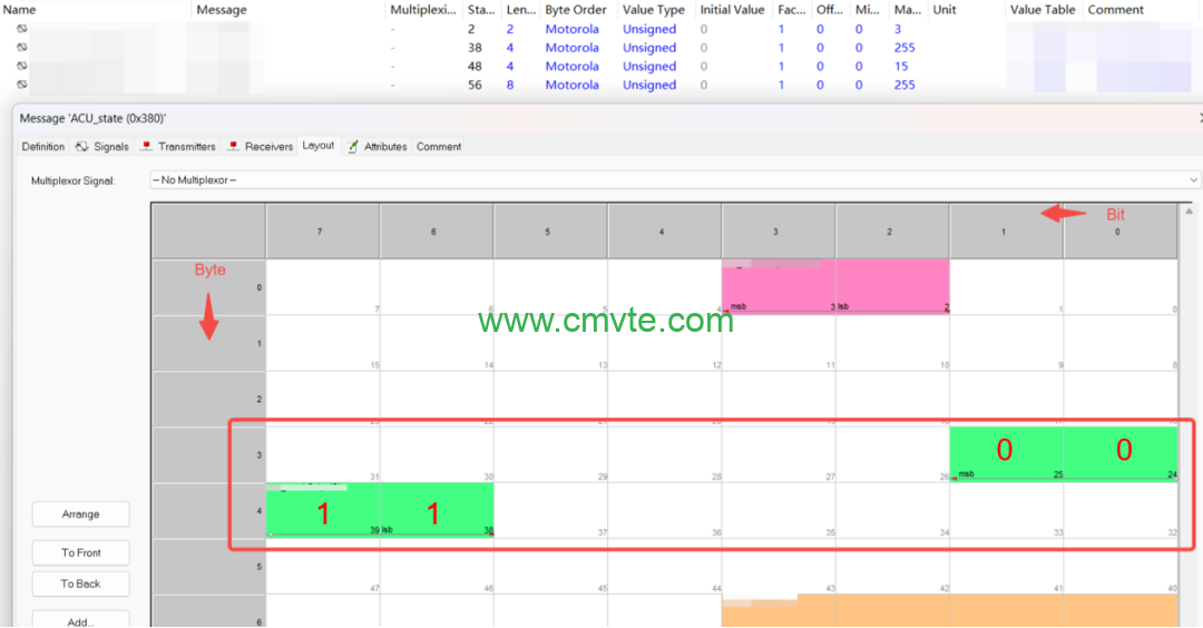
- Single-byte signals are identical in both formats. The difference only appears when signals cross byte boundaries.
- DBC consistency: All signals in a single DBC database should use the same byte order — mixing Intel and Motorola in one DBC causes data corruption.
- LIN is fixed: LIN database (LDF) signals are always Intel (little-endian) and cannot be changed.
Why This Matters for EV Conversions
Every CMVTE motor controller, BMS, and VCU communicates over CAN bus. When integrating our components into your EV conversion, correctly configuring byte order in your DBC file ensures that throttle position, motor speed, battery SOC, and fault codes are transmitted and interpreted accurately. A single byte-order mismatch can cause false fault readings, erratic motor behavior, or communication dropouts.
Our technical team can provide the DBC definitions for all CMVTE CAN-enabled components — pre-configured with the correct byte order so you do not have to guess.


